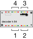
There are accordingly 4 consecutive addresses that can always be accessed on a k84 decoder.
During the configuration process for the signal you can read the appropriate switch settings and the output to be used on the k84 decoder after you have selected the corresponding group of switches (8 switches for the k84 decoder) and then transfer the settings to the signal decoder.
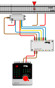
If the signal setting does not correspond to the setting shown on the Central Station, then all you have to do is swap the two blue wires on the mechanism in question.
The Outputs on the k84 Decoder

Connections for a Signal to the k84 Decoder,
here at Outputs 3 and 4.
The wires not connected here are for controlling track voltage. The connections for these wires can be found in the instructions for the signal in question.

